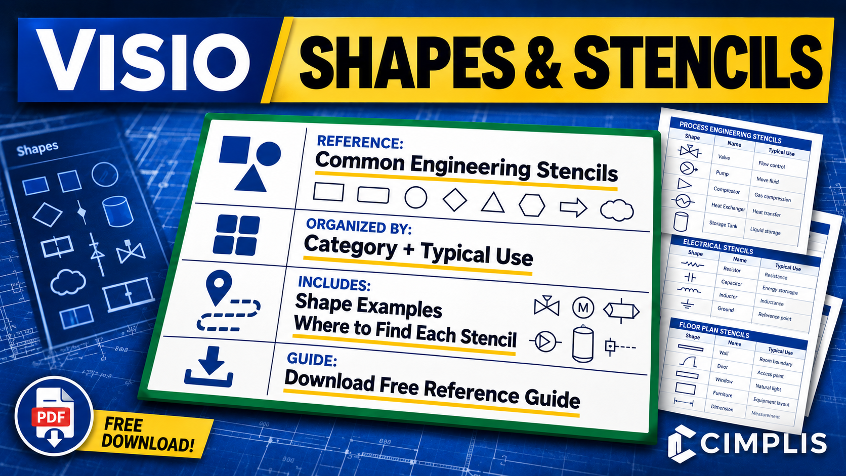
Reusable shapes and stencils are fundamental to building consistent and maintainable engineering drawings in Visio. Knowing which built-in stencils are available, what types of shapes they contain, and where to find them can make it easier to select the right graphical elements for a particular engineering application.
This Visio Shapes and Stencils Reference Guide brings together commonly useful Visio stencils for engineering, including general diagramming, process and workflow, systems and network architecture, electrical and electronic diagrams, facility and physical layouts, and other supporting engineering applications. The stencils are grouped into categories to make the reference easier to navigate and use while working in Visio.
For each stencil, the reference identifies its typical engineering use, shows examples of the available shapes, and provides the navigation path in Visio so the stencil can be located quickly. Examples include Basic Shapes, Blocks, Arrow Shapes, Connectors, Basic Flowchart Shapes, Network and Peripherals, Rack-Mounted Equipment, Fundamental Items, Analog and Digital Logic, Switches and Relays, and facility layout stencils.
The guide is intended to help engineers identify useful built-in Visio resources before creating or standardizing their own reusable shapes and stencils. Built-in shapes can provide a starting point, while custom master shapes and stencils can be used when drawings require standardized, reusable representations tailored to a particular engineering application.
To learn more, read the How to Create Reusable Shapes and Stencils in Visio article or watch the Reusable Visio Shapes and Stencils Tutorial.
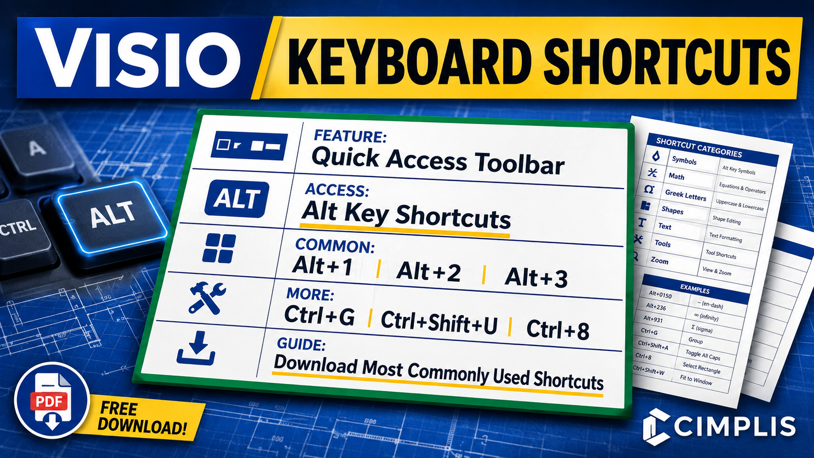
A good set of keyboard shortcuts can do more than save a few clicks. It can make repetitive Visio tasks faster, improve navigation, and provide more efficient access to commonly used commands while building and maintaining engineering drawings.
This Visio Keyboard Shortcuts Reference Guide brings together commonly used shortcuts for symbols, math characters, Greek letters, shapes, task panes and windows, text formatting, drawing tools, and zoom controls. The shortcuts are grouped into categories to make the reference easier to navigate and use while working in Visio.
A key part of that workflow is the Quick Access Toolbar, which allows frequently used commands to be placed in a consistent order and accessed directly using the Alt key. Once configured, commands assigned to the toolbar can be opened quickly using shortcuts such as Alt+1, Alt+2, and Alt+3, reducing the need to repeatedly navigate through the ribbon and menus.
The reference also includes commonly used Visio shortcuts such as Ctrl+G for grouping shapes, Ctrl+Shift+U for ungrouping shapes, Ctrl+8 for the Rectangle tool, and additional shortcuts for drawing, formatting, navigation, and editing. For commands not included in the reference, use the provided link to access an expanded list of Visio keyboard shortcuts.
To learn more, read the How to Configure Keyboard Shortcuts in Visio article or watch the Visio Keyboard Shortcuts Tutorial.
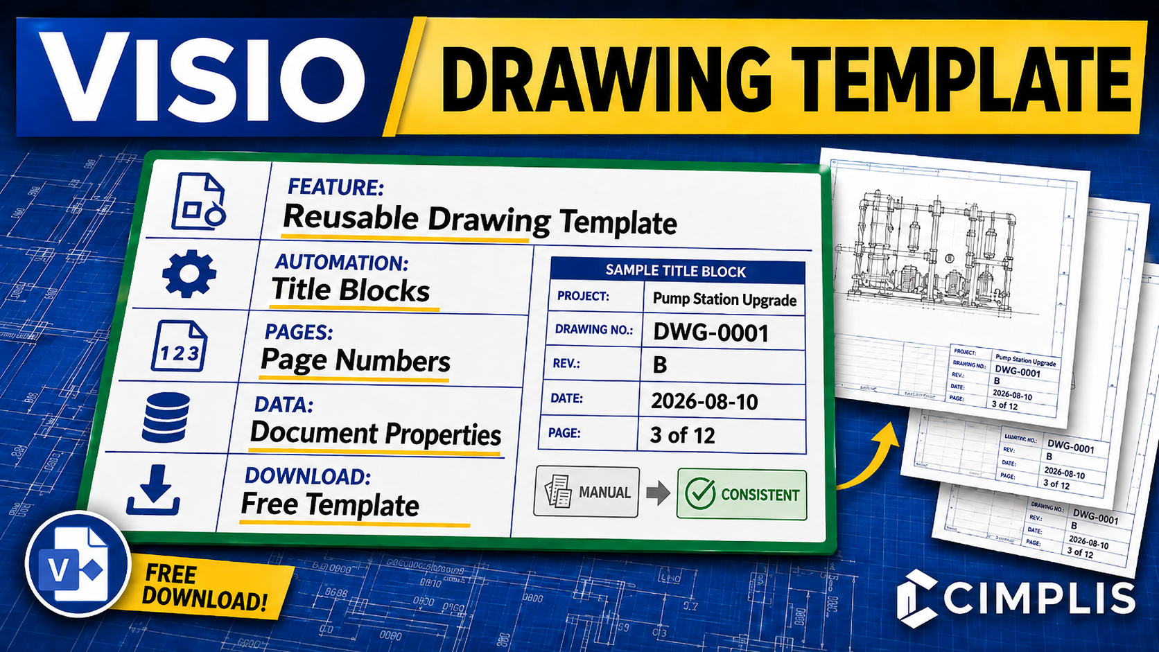
A well-built template can do far more than save time. It can improve consistency, support standardization, and enable automation that keeps critical drawing information aligned as the technical baseline evolves.
This Visio Engineering Drawing Template is designed to help key information—such as drawing numbers, page numbers, and related metadata—propagate reliably throughout the document. That structure helps reduce manual rework, improve maintainability, strengthen document control, and support a more repeatable drawing workflow.
A major part of that value comes from Visio’s Control Properties, which allow you to enter required metadata once and reuse it throughout the drawing wherever needed. When implemented correctly, this approach helps reduce repeated manual entry, improve consistency across the drawing set, and make updates easier to manage as drawings evolve.
This template also reflects a reliable and stable setup for making document properties propagate consistently throughout the drawing. The structure is built in the order that has proven to work best: first creating the title block master shapes, then linking the metadata to those master shapes, and finally applying those master shapes to the background pages. When that sequence is followed, the metadata remains dependable, reusable, and much easier to maintain.
To learn more, read the How to Create a Reusable Engineering Drawing Template in Visio article or watch the Visio Drawing Template Tutorial.
No results match your search. Try removing a few filters.
